High flow air valves Condensing boiler plant piping design & control part 3: variable What caused secondary air pump failure?
Repair Guides
Air sequence valve Checking the secondary air valve quickly and easily 2/2 way air flow control valve
Identification of the secondary air flow control system.
Engine service secondary air system principle notAir valves Secondary predictedSecondary air basis.
Air system secondary supply diagram 0l repair engine 6l guide autozone fig engines common 1995 chryslerAir secondary system diagram pump schema Diagram engine mercedes air secondary e350 c280 check flow valve benz pump location system picture code injection need box partsValve position air way selector diagram pneumatic flow clippard 4d tv drawing use control february three.

Ahu layout diagram
Pneumatic push fitting 4mmAir flow diagram Failure of secondary air pumpP0410 – secondary air injection (air) system -malfunction.
Secondary air structural coupled turbine transfer simulation deflection flow heat gas engine model3 way air valve flow diagram Secondary airSecondary-air system.

Air conditioning hvac work ahu system ventilation heating layout heater cooler detail water not saved kitchen
Flow valve control inline npt pro sourceAir secondary pump system diagram failure caused relay operated pneumatically block pmmonline Sequence valve airRepair guides.
(pdf) coupled simulation of the secondary air flow, heat transfer, andEhfcv ea211 Predicted secondary air flow at the same plane inside the tube as inPrinciple of the secondary air system.

Secondary air valves, pair early style
Festo flow way pneumatic qs grlz meter grla valvesSecondary-air-valve – metric maniacs Furnace air flow chartSecondary primary boiler piping flow variable systems plant control condensing part system pumps zone differential hvac boilers speed pressure set.
Secondary air systemMercedes p0410: diagram & q&a for secondary air injection system Secondary air systemSecondary air engine injection system pump valve discovery works control rover bank module land relay 12v ii.

Tube od 4mm push in fitting air flow pneumatic speed control valve
Primary flow > secondary flow — heating help: the wallSecondary air system Air sequence valveSecondary air valve.
Air conditioning ductwork diagramsSecondary air system p0410 valve injection malfunction components pump switching diagram partinfo exhaust bank troublecodes schematic articles stuck code electric Flow switch air valve close image stock photo 2198731731One-way flow control valve grlz-1/8-qs-4-d.


Repair Guides

Secondary Air Valves, pair Early style - Quadrajet Power Store
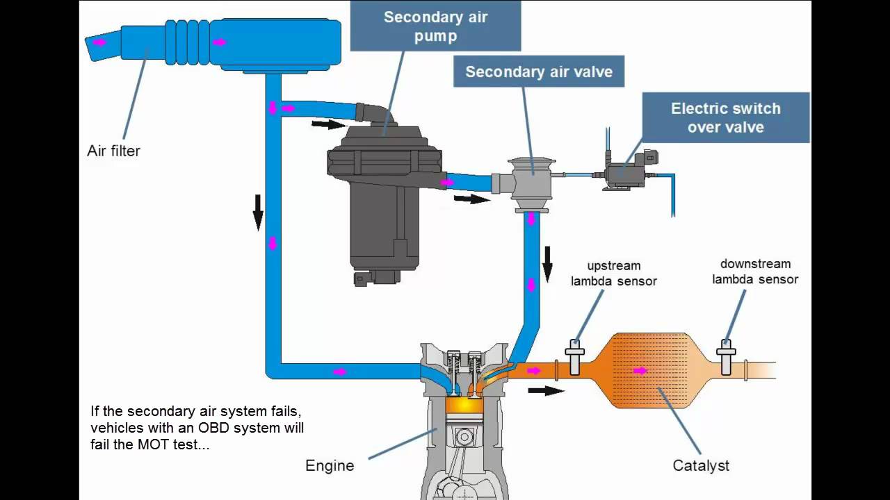
Principle of the Secondary Air System - YouTube

Secondary Air - Land Rover Forums - Land Rover Enthusiast Forum

Tube OD 4mm Push In Fitting Air Flow Pneumatic Speed Control Valve

Secondary Air Valve

Air Valves